Complete structure of 3D printed finger
To put the finger and all components together to complete the physical structure of the Bionic finger, you will need all components mentioned in the materials page. You can find that here.
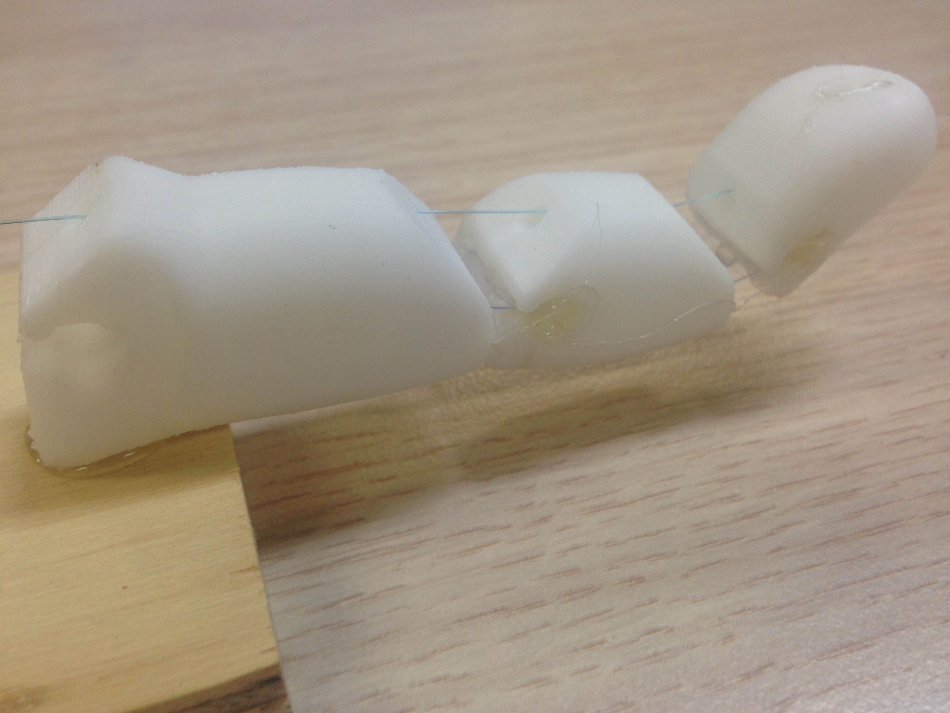
1. Have the square of acrylic sheet and the 3 finger parts ready and a pair of scissors, cut the acrylic sheet into two 1cm by 1.5cm squares.
2. The 3D printed parts all have holes down one side of the finger, place them flat on the table with the holes facing up, with the largest at the bottom and the finger tip like one at the top and the medium one in the middle.
3. Then you will need a hot glue gun with glue preheated. You will then place the thin piece of clear plastic between the two finger in the slits of the finger to form the joint.
4. Secure this in by putting hot glue in both slits while keeping the acrylic peice straight.
5. Repeat this for the other joint.
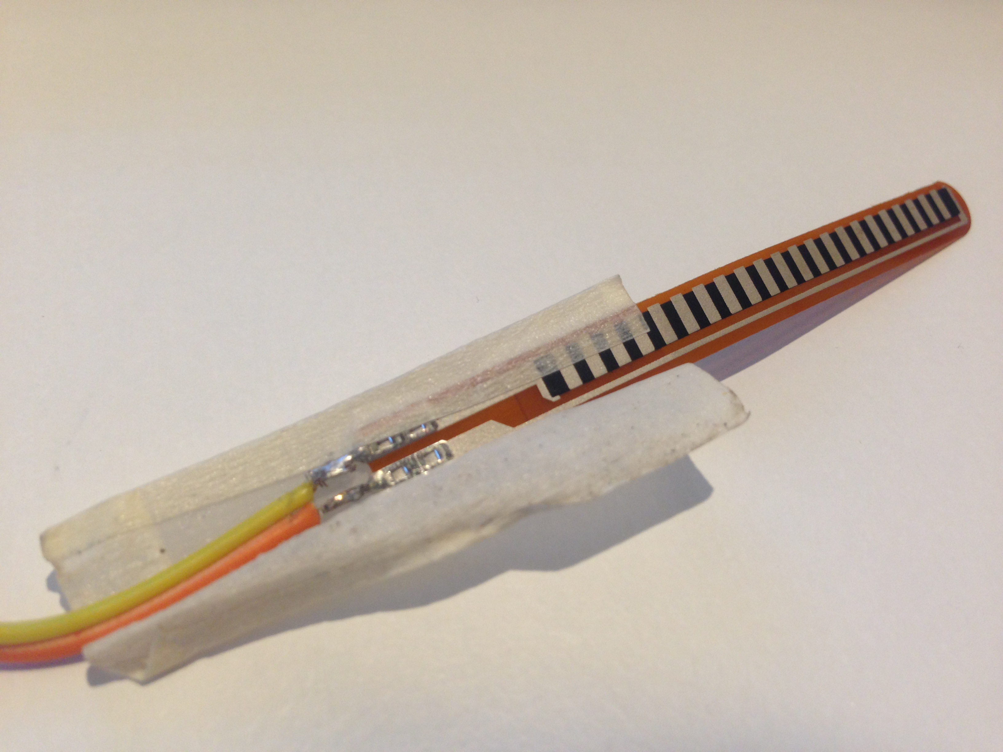
1. You will need the two Arduino wires, tape and the flex sensor.
2. On the flex sensor there is two metal wire spikes coming of the bottom the flex sensor, find this as this is were the wires need to be connected.
3. The attachment can be done by attaching the metal spike of the flex sensor and the metal of the Arduino wire, twisting and making sure the stay touching and then taping down.
1. Have a hot glue gun preheated before beginning.
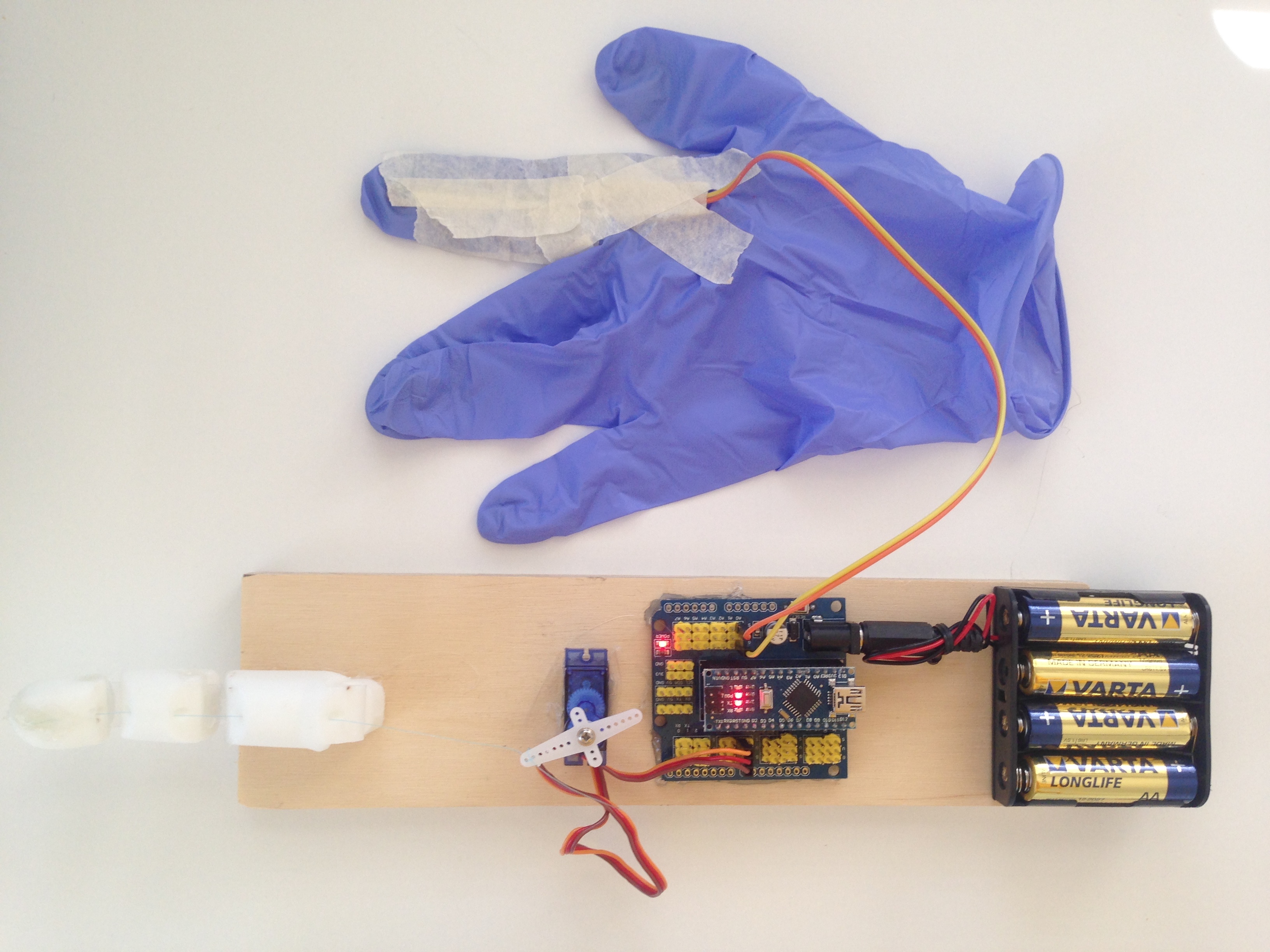
2. Start by placing the battery back on the end of the wooden board, you will then hot glue it on with half of the battery pack hanging off the board. refer to photo below
3. Place the Arduino Nano on the board next, with enough room for the battery pack plug to be plugged in and out, then hot glue this to the board. Make sure you only use the hot glue along the edges and areas with no equipment. (areas with no metal circles, just plain plastic.)
4. The servo is then hot glued to the board around 0.7cm from the Arduino board so that the longer edge is facing the Arduino.
5. After completing the steps to make the 3D printed finger above, hot glue the first and longest part of the finger to the board and let the middle and tip of the finger hang off.
6. Then connect the flex sensor to the Arduino board, the two wires are place on either {G, A0} or {S, A0}. This is loacted on the side with the black battery connection is is the first yellow row in.
7. The servo wires are then connected to the Arduino with the brown wire going in into the {G,6}, with the rest being placed in the corresponding points to the wire input mechanism. This is loceted on the opposite side than the flex sensor.
8. The wire can the be attached to the servo’s shaft arm and threaded through the holes in the 3D printed finger and then the wire/string is glued to the tip of the finger to be secured.
9. The flex sensor can then be attached to a plastic glove so that when the glove is on a hand and fingers are bend the flex sensor spine (the black and white stripes) is the part touching the glove.