Use this to code the Servo Motor
For this finger to work there is two codes that needed to be uploaded to the Arduino, the calibration code and servo code.
The program used to code this is Arduino, this is needed and can downloaded here.
Download the software that correlates and works with your computer.
1. Once the Arduino program is downloaded open the program and make sure you set the board to the correct Arduino you are using in the tools section at the top of the program. i.e. if you are using an Arduino Nano then it should say, Board: “Arduino Nano”.
2. The code for the servo motor should be done first to make sure the servo moves correctly before trying to calibrate the flex sensor with it.
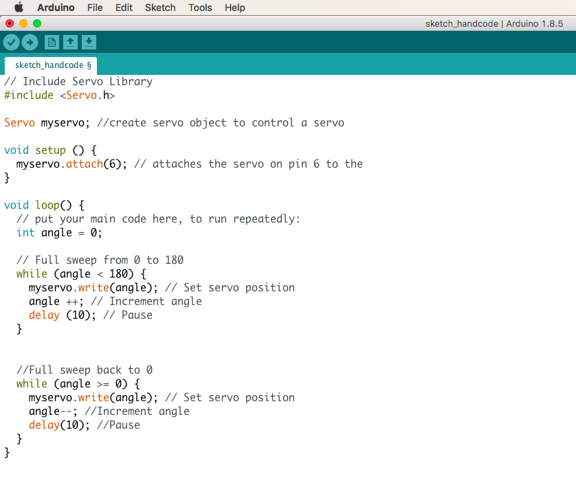
3. The use the code below, under 'Servo motor code', makes the servo arm move and is needed to uploaded to the Arduino first. For an explanation of this code click here.
4. The next code, found at the bottom of page, calibrates the flex sensor and the servo motor and this code is the next to be uploaded. For an explanation of this code click here.
In the first three lines, the code is setting the program up, name it, give access to the Arduino board to control the servo motor.
The void setup helps to setup the connection between the servo and Arduino board. The number 6 is referring to the line 6 that the servo wire is inserted on, in the Arduino board.
The void loop signals that the program between the curly brackets is on repeat and loop consecutively unless turned off. The angle is set at 0 to be the beginning integer that the servo begins at.
The next code found under 'full sweep from 0 to 180', then makes the servo have the ability to move from 0 to 180 degrees and have a short pause between returning back.
The code below 'full sweep back to 0, then states that the servo should then sweep back to the start of 'integer 0' and have a short rest to then repeat the process continuously over.
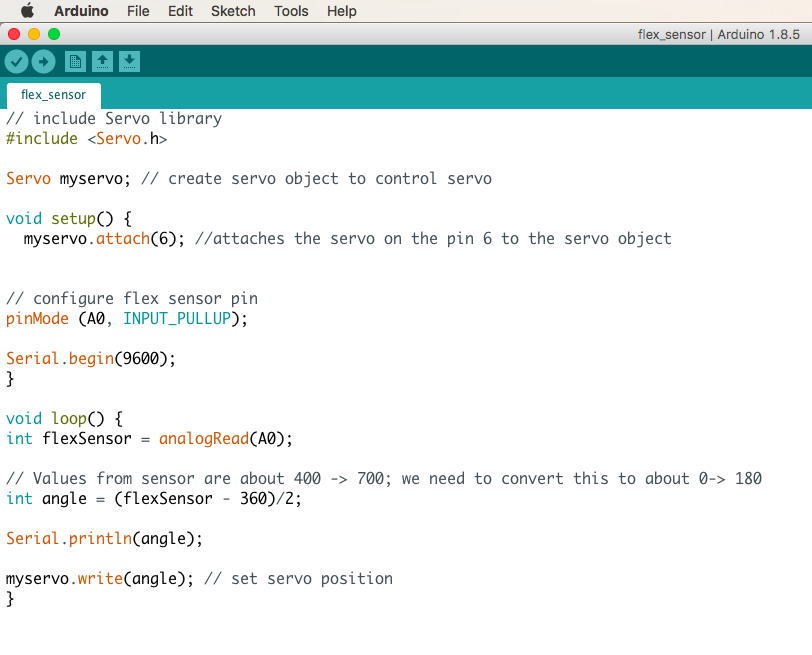
The beginning three lines of the code helps to set the program up, name it, give access to the Arduino board to control the servo motor.
The void setup helps to setup the connection between the servo and Arduino board. The number 6 is referring to the line 6 that the servo wire is inserted on, in the Arduino board.
The next lines under, ‘configure flex sensor pin’, makes the pin mode for analogue 0 (AO) is an input_pullup. My flexi sensor is connected to the AO on my Arduino board, thus this makes the pin AO an input and enables the internal pull-up resistor.
The serial begin statement initialises the serial communications between the Arduino board and the computer and the number 9600 is the amount of data per second. 9600 must also be the same number shown at the bottom of the serial monitor for it to work.
The void loop initialises the program between the curly brackets is on repeat and loop consecutively unless turned off. In the line beneath that, the flex sensor is being connected to the the Arduino board as the flex sensor wire is connected to the A0 pin on the Arduino board.
in the code below, // Values from sensor..., The calibration between the flex sensor and the servo motor is occurring. Because the servo has a turn range of 0 – 180 degrees, we must have a line of code that tells the Arduino what angles we want to servo to be able to move. All flex sensors have different values, mine worked best when 360 was taken away from the flex sensor value and then divided by 2. (flexSensor - 360)/2; When 360 is divided by 2 you get a value of 180, and thus a range of 0 -180.
In the statement, ‘serial.print..’, it is telling the Arduino to print the angle numbers created from the movement of the flex sensor, in the serial monitor which is a separate window showing the data received from the flex sensor.
The code, ‘myservo.write…’, is setting the angle of the servo and controlling the angle of the servo accordingly to the angles being printed by the serial monitor. The closed curly bracket is then finishing the void loop that was started before.